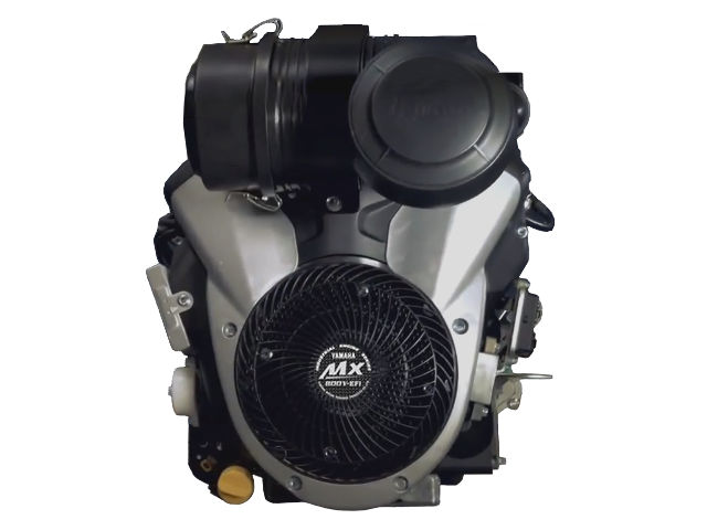
 The Yamaha MX800V-EFI is a small (824 cc, 50.3 cu-in) V-twin air-cooled four-stroke internal combustion gasoline engine with vertical shaft, manufactured by Yamaha.
The Yamaha MX800V-EFI motor has two-cylinder, overhead valves and a ball bearing supported P.T.O. The engine is equipped with an industry-standard air filtration system; electronic fuel injected system (Delphi Multec-EFI); ECU controlled electronic ignition coils and an electric starter.
The cylinder bore and the piston stroke is 80.0 mm (3.15 in) and 82.0 mm (3.23 in), respectively. The compression ratio rating is 9.1:1. The MX800V-EFI produces 31.6 PS (23.6 kW) at 3,600 rpm of maximum gross power or 31.0 HP (23.1 kW) at 3,600 rpm of gross rated power (SAE J1995) and 65.3 Nm (6.66 kg·m, 48.2 ft·lb) at 3,100 rpm of torque.
General information
| Engine Specifications | |
| Model | MX800V-EFI |
| Type | 4-stroke, OHV, V-twin |
| Displacement | 824 cm 3 (50.3 cu-in) |
| Max. horsepower | 31.6 PS (23.6 kW) at 3,600 rpm |
| Max. torque (crank PTO) | 65.3 Nm (6.66 kg·m, 48.2 ft·lb) at 3,100 rpm |
| Fuel system | Delphi Multec – EFI |
| Cooling system | Forced-air |
| Ignition system | ECU Controlled Electronic Ignition Coils |
| Lubricating system | Full pressure with filter |
| Starting system | Electric starter |
| Stoping system | Misfire |
| Fuel used | Unleaded gasoline (octane number 86 or higher) |
| Fuel tank capacity | – |
| Fuel consumption | – |
| PTO shaft rotation | Counterclockwise (from PTO shaft side) |
Service Information
| Engine | |
| Maximum speed | 3550-3600 rpm |
| Cylinder compression | 13.4-14.8 kg/cm2 (190-210 psi) |
| Valve clearance | |
| Intake valve | 0.07-0.13 mm (0.003-0.005 in) |
| Exhaust valve | 0.07-0.13 mm (0.003-0.005 in) |
| Oil system | |
| Oil type | Yamalube 4-stroke or an equivalent (SE or higher) |
| Recommended oil | SAE 10W-30 |
| Oil capacity | 2.0 L (2.11 US qt, 1.76 Imp.qt) |
| Ignition system | |
| Ignition timing | BTDC 30° / 3750 rpm |
| Spark plug | NGK: BPR6ES |
| Spark plug gap | 0.7-0.8 mm (0.028-0.031 in) |
| Spark plug tightening torque | 20 N·m (2.0 kg·m, 14 ft·lb) |
Valve clearance adjustment data
Calculate the thickness of new adjusting pad so valve clearance comes within specified values.
R = Thickness of removed adjusting pad
N = Thickness of new adjusting pad
M = Measured valve clearance
Intake/Exhaus:
N = R + [M – 0.13 mm (0.005 in)]
Adjusting pads are available from 1.80 mm (0.0708 in) to 3.00 mm (0.1181 in), in steps of 0.05 mm (0.002 in).
Example:
R = 1.80 mm
M = 0.22 mm
N = 1.80 + (0.22 – 0.13) = 1.89 mm, round to 1.90 mm, so we need a adjusting pad with code 190.
Adjust valve celarance at 1000 hr periodic maintenance, normal operational range between periodic maintenance may be 0.02-0.2 mm (0.0008-0.01 in)
| Tightening torque | |
| Rocker arm shaft bolt | 4.0 Nm (0.40 kg·m, 2.9 lb·ft) |
| Cylinder head cover bolt | 11.0 N·m (1.1 kg·m, 8.0 lb·ft) |
Be the first to comment